
I’ll not re-iterate detail about the work on a ping tester I’ve been slaving over, using up all my spare time for the past week as it is in the previous blog entry, but here are thoughts worth showing re: the experience.
So, several things… the ESP8266, long claimed to be past it’s sell-by date is alive and well here at Bedrock. I have every imaginable variation on the ESP32 lying on my desk including the large WROOM module and the tiny C3 and S3, S6 units.. I’ve also dragged out some older ESP8266 modules, one here has been hiding in a cupboard for the past 2 or 3 years at least.
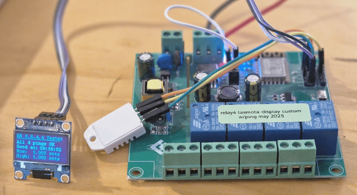
See the lead image above – this old board arrived as a generic ESP8266 4-relay board with a choice of 5v in, 9-12v in or mains power in – and 4 totally independent relay contact sets. Shame I’d not gotten a pretty box for it at the time. It’s so old I can only guess it may have come from AliExpress but as commented later – they still sell the same board.
Next time someone tells you the ESP8266 is dead, it is currently running Tasmota-display with the PING #include (more about that in a second), handling the 4 relays, a common AMD temperature/humidity sensor, the SSD1306 128*64 display and there’a a pin left for a WS2812B RGB LED strip should I need/want it – all without breaking a sweat.
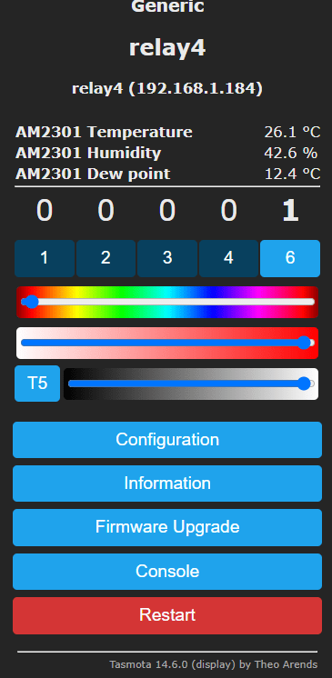
Of interest here’s the webUI and the config… You can see I’ve already set up the WS2812, just not connected in the photo.
So this is standard Tasmota with one variation. The RGB control shown doesn’t really cover what this setup could do… the WS2812 control allows individual control over each RGB LED or group control including some simple effects such as RAINBOW – my favourite – I use that a lot.
But I digress – here is the config… Oh and I get that address display by using (non-volatile) SO53 1 in the Tasmota console.
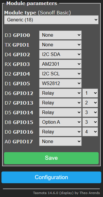
Note that serial comms isn’t possible as I’ve used one of the serial lines for the AMD2301… note also that care is needed with GPIO choice as not all ESP8266 GPIOs are the same. SCL and SDA facilitate the OLED display.
Ok the ESP8266 doesn’t have Bluetooth and the ESP32 is a little faster (though remember, the clock on the ESP8266 can be doubled – I’ve not felt the need to do that since introducing the command in my now-defunct ESP-GO firmware for the ESP8266, gone in favour of Tasmota (and ESP-Home from time to time).
That 4-relay board is still floating about on AliExpress for something like 8 Euros and as an aside, ESP8266 D1 Mini boards for well under 2 Euros.
All of the above runs on standard off-the-shelf Tasmota EXCEPT for the PING command I use to check on my broadband. That needs a custom Tasmota and if you take a look at my previous blog entry you’ll see that creating a customer version needs no installs – no software in the PC and takes a couple of minutes before you can download the Tsamota you need (handy to remember to rename it – I used the tasmota-display model and renamed my download tasmota-display-ping.bin.gz) and you also need to grab Tasmota-minimal.bin.gz – don’t go for the .bin versions or skip the minimal – for fear of getting a dreaded “out of space” message. So, all easy stuff given the info I’ve put up. Really – SO easy to make a custom version – all you have to do is ermember not to OTA update it in the futuer with a standard Tasmota or you lose the additional functionality.
BUT (and here’s where the cautionary tale comes in), the ESP8266 doesn’t support the BERRY console that is readily available on the ESP32 – no big deal, I cannot make head nor tail of it. So in my previous blog and in the photo at ythe top, you’ll see that Tasmota on the ESP8266 supports variables as seen in the display – the only annoyance is that they come up in floating point (I have no use for fractions as my display shows number of successful broadband pings) – and you can’t do anything about it – the rules system simply will not do functions like INT or ROUND.
Yesterday I shortened by life by spending hours listening to Perplexity AI tell me how to get around that by further customising Tasmota to include a file system and functions like the above and more. All good except that the supremely confident, oft-repeated instructions from the AI simply did NOT work.
If the AIs were a little less confident of their own perfection I might be more forgiving but Perplexity kept giving me the wrong answers followed by detailed explanations as to why the answers were correct. Not only that but it would come up with a “solution”, I would get half way through reading it before it was deleted off screen while the AI went off to write War and Peace ending up with re-iterating the “solution”.
I finally told it to STOP giving me breakdowns – that was after I realised it was using – amongst others, my own blog as a reference – how dumb is THAT – using info from a guy who is asking the very question the AI is seeking to answer. In the end it stopped giving me all the nonsense and proceeded to give me more solutions that didn’t work. I gave up and went back to old-fashioned thinking. It could not even remember not to give me breakdowns for more than 10 minutes – “in future I will give you only concise answers until you tell me otherwise” – yeah, right. The end result of that is I’m still convinced that mathematical functions in rules on the ESP8266 are a non-starter – hence the decimal points in the image above. Oh, well. Getting that far took HOURS to get no-where. If I were doing this for a living I’d not be popular with the boss. Now if anyone has first hand, detailed experience to the contrary – please do comment. I’d love to get rid of the trailing zeroes in my display.
Incidentally, a quick hover over the Tasmota options in the FLASH Tasmota page makes it clear that neat as they aer, some of the smaller ESP32 boards do not get full support from Tasmota – a casual look and you might say – oh, just use Tasmota32-display – works on all ESP32 boards – erm, no it doesn’t and once again the AI failed to give me a working explanation as to why not.
All in, despite the difficulties – I feel I’m a lot more knowledgeable on the subject than I was a week ago – that has to be a good thing. Between these two blog entries, anyone interested should be able to duplicate anything I’ve done – should the urge take you. If not, well I hope this was of some interest,
November 2025 Update
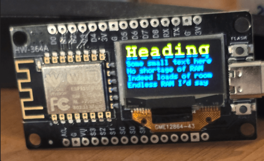
More caution I’m afraid. I have a nice ESP8266 board in front of me – see photo – currently showing some random text and the time and date on a built in 128*64 SSD1306 – these boards are CHEAP.
I just wasted a day using ChatGPT (which being the free tier usually runs out half way through a tricky problem and tell tells you to come back tomorrow) and my new favourite, Gemini CLI which works a bit like ChatGPT but on the command line in PowerShell and does not immediately run out when you hit a problem. That said, both of these tools have some severe problems. One of which is becoming increasingly annoying: confident, “Tested” answers that are nonsense. Telling you it has a tested working solution for something when in fact it’s not a solution at all. This happens more than we’d all like to admit. Fortunately I do know my tech and usually have an inkling when I’m being fed nonsense.
Anywhere, I was trying to get the board you see in the photo above to show some text using ESPHome. The AIs kept coming back and telling me that the ESP8266 is very short of resources, something I knew from many years of experience to be absolute rubbish and I believe is, in, this case more down to the severe bloating in the ESP home software. Anyway, after hours of chatting away to the AI, I could not get what I wanted, which was a decent several lines of simple text on the display. I just gave up and went back to good old Tasmota.
It’s a little while since I’ve used this particular combination of Tasmota, ESP8266, and SSD1306, but I didn’t want to see this board go to waste. I have several of them that I got from AliExpress for next to nothing.
So, forgetting that I’d already cracked this a long time ago, I went in setting display type and display mode and tried to put some text into the display. Absolutely nothing came out. What a disappointment.The AI wasn’t a great deal of use, so I went back to my old standby, a very helpful fellow by the name of “sfromis” in the Tasmota forums and as usual, he got me out of a mess. The AI was trying to tell me I needed to set up displaymodel 0 and displaymode 1 for the SSD1306 (in the Tasmota console. Utter and complete nonsense.
First things first, these days I’m using Tasmota firmware version 15 as an example. They have a universal display driver in Tasmota. That would be displaymodel 17, but you don’t set it. Instead, you use up one part of the rule space inside Tasmota to store some code (not an actual rule). You don’t have to set up the rule or turn it on. All you do is use the console to dump the code below into the right place. But I’m jumping in too early here. Firstly, this display uses GPIO 12 and 14 for I2C. And you have to set that up in the config.
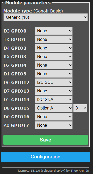
Here’s the basic setup – for this display they use GPIO12 and 14 for I2c and you ALSO have to use any old unused pin and set that to “OptionA 3” – I’m not entirely sure why but its probably to do with the next stage – the stored configuration.
Tasmota allows for up to 3 rule sets (that’s not 3 just rules but 3 rule sets). As it happens you can put some numbers in JSON format into rule 3 to make the SSD1306 work. I’m using a 128*64 display, there is a minor variation for 128*32 displays.
Firstly, set module type for Tasmota to “Generic 18”. Then, fill in those three configuration entries as I’ve done here above left. If your display is using a different location for SDA and SCL, change the pins accordingly. That is almost all you need to get going. We just have to fill in rule 3 at the console as I mentioned, and rule 3 does not have to be turned on. You simply put the data in rule 3 exactly as you will see below.
Rule3 :H,SSD1306,128,64,1,I2C,3c,*,*,* :S,0,2,1,0,30,20 :I AE D5,80 A8,3F D3,00 40 8D,14 20,00 A1 C8 DA,12 81,9F D9,F1 DB,40 A4 A6 AF :o,AE :O,AF :A,00,10,40,00,00 :i,A6,A7 #
That’s it – no displaymodel setting. For a quick and easy test you might want to set displaymode to 1 – again in the console – It will show the time from power-on – all of this is non-volatile so the displaymode, config and rule3 data be there next time you turn on your ESP8266.
Reboot and the board should show the time – that’s what I meant by a quick test. Once done, set the displaymode to 0 and reboot – you should have a blank screen.
The next step is to DO something with your cheap display. At the console enter this:
[z]Hello[x0y16]This is a test
So commands sit inside square brackets. Z means clear screen, x0y16 should be self explanatory and as the power-up cursor default is 0,0, no need to set that for you first line after a clear screen – though you can. You can also add time and date – but for all of this and more- don’t go wasting your time with AIs which may have out-of-date information. It’s all here at the Tasmota commands page in the display section.
Now lest you think I got all of this sorted myself – here is my query and “sfromis” response. Here is the Tasmota display section. In that display section you’ll find the correct way to enter time and date on your display as I’ve done above. Tasmota has changed over the years, and by using the Tasmota commands page, you will always have the latest information. I’m now all set and my next job is going to be to add an I2C temperature, humidity, and pressure sensor. I will add the BME280 to this board, and of course already having the I2C activated, it’s not going to use that much room as against a bit-banging solution. If this helps you – enjoy.
If you want the 32-line version of the code for rule3… it is:
:H,SSD1306_128x32,128,32,1,I2C,3c,*,*,* :S,0,2,1,0,10,10:I AE D5,80 A8,1F D3,00 40 8D,14 20,00 A1 C8 DA,02 81,8F D9,F1 DB,40 A4 A6 AF :o,AE :O,AF :D,81 :A,00,10,40,00,00 :i,A6,A7 #
But lastly, if you think I’m being overly dismissive of current AI (which I use a lot to make caricatures and to be fair, sometimes a bit of coding) – take a look at this from Google..
2. Configure the time server and timezone
- Go to the Tasmota console.
- Set the NTP server to a server close to your location for better accuracy, such as
pool.ntp.org.- Command:
ntpserver1 pool.ntp.org.
- Command:
- Set your timezone offset from UTC in seconds. For example, a timezone that is UTC+2 would be
7200(2 hours * 3600 seconds).- Command: ntp offset 7200.
- Save the settings.
3. Display the time and date on the screen
- Use the
DisplayTextcommand to show the time and date. - Use the TimeFormat and DateFormat commands to set how the time and date are displayed.
- Example: TimeFormat 24.
- Use
DisplayTextwith a command string containing the date and time variables. - This command will display the time in 24-hour format on the first line and the date on the second line.
- The
%H,%M,%S,%Y,%m, and%dare Tasmota format codes for hour, minute, second, year, month, and day.
- The
Most of that is utter nonsense. It also told me to go off to timeservers – all I ever do is set timezone to 99 in the console
.Ok, almost COMPLETELY off-topic: Months ago I asked ChatGPT about the now defunct pub “The Royal Sovereign” in Tynemouth UK. ChatGPT swore blind it never existed… today, Gemini-Cli says the same…
Based on my search, there is no specific mention of a pub named “The Royal Sovereign” in Tynemouth. There is a “Royal Sovereign Freehouse” in Brighton, but that is a different location.
Based on my research, there doesn’t appear to be a pub officially named “Sovereign” or “The Sovereign” in Tynemouth. There is a pub called “The Sovereign” in Shepley, Huddersfield, but not in Tynemouth. It’s possible it might be a local nickname, a former name, or a misunderstanding.
I’m still unable to find any information about a defunct pub named “Sovereign” or “Royal Sovereign” in Tynemouth, even when specifically searching for pubs from the 1970s. It’s possible the pub had a different name, or the name “Sovereign” was a local nickname. Would you like me to search for other popular pubs in Tynemouth during the 1970s, or perhaps pubs with similar-sounding names?
Check out the image below… and there seem to be conflicts even in that article – see “The Sovereign Pub… is now the Tynemouth Castle Inn” followed by the block claiming “The Tynemouth Castle Inn, formerly known as the Park Hotel”.
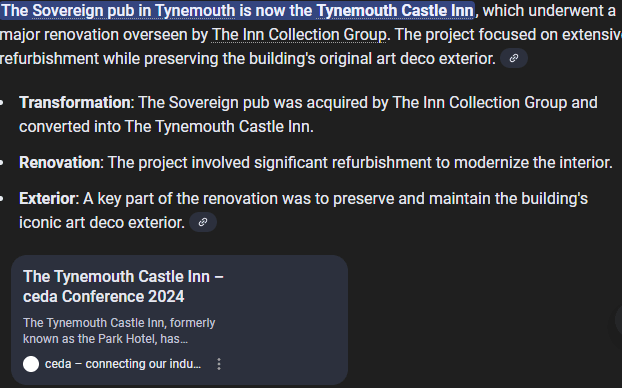
Interestingly the “Tynemouth Castle Inn” is indeed the former Park Hotel (Tynemouth – not Cullercoats – Google Maps agrees with me) – nowhere NEAR the old Sovereign pub. From one to the other was a solid 10 minute walk I did MANY times
Check out the image below – thankfully a real person’s FB post confirms my memory, complete with photograph.
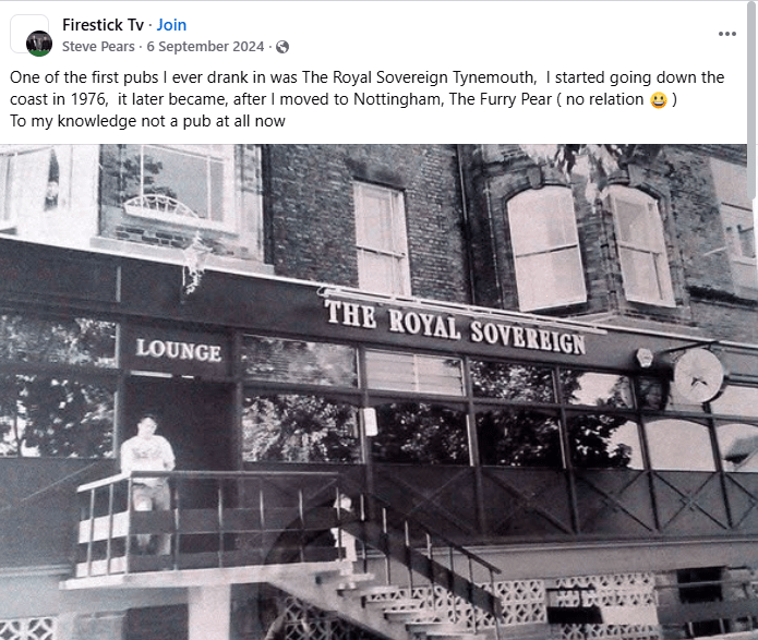
I can confirm the Sovereign was around in the 1970’s and specifically I remember blasting AC/DC Rock and Roll ain’t Noise Polution on the jukebox night after night. That track was/is on the 1980 AC/DC Album “Back in Black”.
Rather worrying that I can remember that far back clearly yet we are sleep-walking into relying on these very flawed AI tools – That photo + description above is openly available on Facebook . It is also safe to say I went to that very popular pub most Fridays from 1971 until at least 1980 as I lived in Tynemouth.
More relevantly, due to lack of use I’d forgotten that years ago I used that “rule3” code on an ESP8266 yet Gemini had no clue (it’s on the Tasmota-related forums).
Hi Peter
I have several of those 4 channel relay boards. I bought the first to switch my garden pond electrics and was so impressed I bought a few more – just in case! Even at their current price of £10 (Ebay) they’re a real bargain, I couldn’t build something for less!
I’m currently doing some renovation work on my house and a recent challenge was to revamp my kitchen lighting. My kitchen has one central light which I’m replacing with three lights, actually three groups of six mains powered LED downlighters but that’s not really relevant.
My house has solid brick walls and I know from bitter experience that chasing them to install new wiring isn’t fun so I was very keen to avoid this! Besides, this is 2025! I wanted something smart!
To cut a long story short I already had most of the bits I needed, the relay card & a 433MHz three gang switch:
https://www.ebay.co.uk/itm/275762015793?var=577337063088
The switch is powered by a 23A 12v battery which is easily changed when the need arises. It’s a little ‘cheap’ in construction but it’s not bad! Has excellent range! And it cost a fiver!
I originally thought I’d write the code myself but as a recent ‘convert’ to Tasmota I thought I’d give it a try:
Tasmota supports 433MHz devices using the RCSwitch library. BUT you NEED the ‘Tasmota sensors’ variant. Lesson one!
There is a very terse example of using a 433MHz receiver rule in the Tasmota documentation:
ON RfReceived#Data= DO ENDON
Easy? No! It’s easy to catch the codes from the switches in the Tasmota console. Implementing a suitable rule took hours! Like you, I find the rules slightly less than obvious! Thankfully there are people out there fluent in Tasmota!
So, an actual (working!) rule looks like this:
on rfreceived#data=0x0000000000DBE012 do power1 toggle endon
My switches use a 24 bit code (the DBE012 part) BUT apparently this is a STRING comparison which expects a 64 bit number as the string. Don’t ask me! I think it’s bizarre! I was meant to guess this?:)
I’m not about to moan about Tasmota. It’s really good, and it’s free, but not perfect!
Conclusion: This works perfectly on my living room floor! I’m fitting it very soon. Using Tasmota provides a web interface as well as MQTT.
As a complete aside, my fingers were quite sore from twisting wires for choc blocks so I bought a ferrule crimper. It’s great!
ON RfReceived#Data= DO ENDON
Your blog doesn’t like angle brackets?
Clearly not. This isn’t what I sent.
TRy sending me an email and I can get the code into a block for you. I use WordPress…. Github isn’t the easiest place to get accurate code either. the email I got from you shows on rfreceived#data do endon -ie nothing between do and endon – which incidentally is not case sensitive – I’ve done a lot of rules in the
past week 🙂
try something like this (and learn how to use raw rf data on tasmota, if you want better results):
rule1 on RfReceived#Data=86CE92 do publish cmnd/comodino/power1 toggle endon on RfReceived#Data=86CE94 do publish zigbee/3tasti/porta toggle endon on RfReceived#Data=86CE91 do websend [192.168.1.114] power2 toggle endon
it uses mqtt publish to send data elsewhere, and power toggle the second relay of an other tasmota device, by ip
Have you checked this? I’m fairly sure it doesn’t work.
Try it & let me know how you get on.
it’s perfectly working on a daily basis on my rfbridge, directly copied from there… if you don’t believe me, I suggest you address any issue you’re having to tasmota discord servers, where well proven tasmota experts will help you solve them…
Hi Antonio, this is odd. My original attempt looked rather like your script & didn’t work. As you suggest, and as I indicated in my post, I sought advice.
I was advised that the comparison was a string & not a 24 bit number which my RF device provides.
Tasmota likes this for me:
on rfreceived#data=0x0000000000DBE012 do power1 toggle endon
It does NOT like:
on rfreceived#data=0xDBE012 do power1 toggle endon
How does this work for you but not me? Why is my data 64 bit? Tasmota tells me it’s 24 bit but reports it as a 64 bit number in string format.
Thanks for your input.